INQUIRY
Inquiry
Form loading...

How to Choose the Right Aluminum Extrusion Profile?

Choosing the right aluminum extrusion profile is more than selecting a shape from a catalog. The section must support expected loads, fit the available space, and allow practical assembly. A narrow slot may hold a fastener neatly, yet leave too little room for installation tools. Small details matter.

The phrase Aluminum Profile Aluminum Extrusion appears in product searches, but the right choice depends on the application, not the keyword. Consider the profile’s dimensions, wall thickness, alloy, and temper together. These factors influence strength, weight, surface finish, and how easily the part can be machined or joined. Environmental conditions matter too. Outdoor exposure, moisture, and temperature changes can affect material and finish decisions.

Clear requirements make comparisons more reliable. Define the load, span, connection points, dimensional tolerances, and finish before reviewing supplier drawings. Ask how the profile will be cut, drilled, assembled, and inspected. If possible, evaluate a sample in the intended assembly; a drawing alone may not reveal awkward access or fit. Not every feature earns its place. A custom channel can solve a real problem, but unnecessary complexity may increase tooling cost and lead time.

This guide explains how to weigh those trade-offs and discuss them with an extrusion supplier. Some choices remain imperfect: lighter sections may reduce stiffness, while thicker walls add weight. The useful answer is the profile that meets verified needs without overdesign.
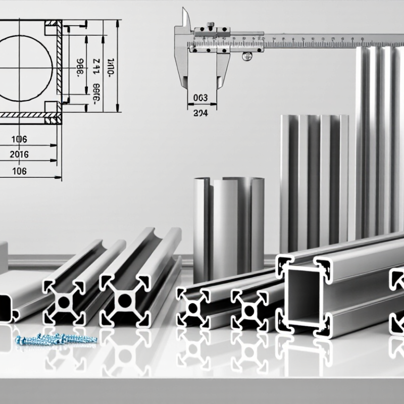
How to Choose the Right Aluminum Extrusion Profile?

Define the Profile’s Function and Operating Environment

Choose the profile by starting with its job: support a load, guide motion, enclose wiring, or transfer heat. Translate that job into measurable requirements, including force direction, deflection limits, mounting points, and space for fasteners. A narrow wall may suit a light cover but buckle under a cantilevered load. Small details matter. Also consider how the profile will be cut, joined, cleaned, and replaced; an intricate cavity can complicate inspection or trap water.

The operating environment can change the right choice. Typical aluminum expansion is about 23 µm per meter per °C, according to ASM Handbook material data. A two-meter profile exposed to a 60°C temperature swing could grow roughly 2.8 mm. Allow movement at joints, especially near glass, machinery, or rigid supports. Salt spray, condensation, cleaning chemicals, and abrasive dust also affect alloy, finish, drainage, and maintenance needs. The International Aluminium Institute reports that recycling aluminum uses about 5% of the energy required for primary production, so designing for disassembly can support material recovery.

Tips: Write down the actual temperature range, loads, and exposure before comparing profiles. Check one real assembly, not just a drawing. A detail that looks efficient on screen may be awkward to clean or install.
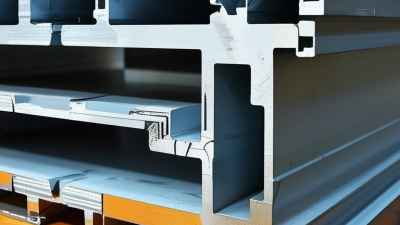
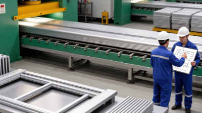
Determine Load, Strength, and Deflection Requirements

Choosing an aluminum extrusion profile starts with the forces it must carry, not its outside dimensions. List the weight of the part, any attached equipment, and forces from movement or impact. Include where each force acts. A load near the center of a long beam can cause more bending than the same load close to a support.

Measure the unsupported span and identify how the ends are fixed. A beam resting on two supports behaves differently from one clamped at both ends. Define the maximum acceptable deflection, too. A few millimeters may be harmless in a guard frame but troublesome for a sliding door or sensor mount. Small movement matters.

Compare candidate profiles using their section properties, especially the second moment of area, rather than judging strength by appearance. Deeper sections often resist bending better, but added material can increase weight and cost. Check the alloy and temper, fastener locations, and local wall thickness; a strong profile can still deform around a bolt. Manufacturer tables are useful, but verify their assumptions about span and support conditions. Early estimates are rarely perfect. I would revisit them after sketching the real assembly, including joints and accessories. For a safety-critical frame or a heavily loaded structure, have a qualified engineer check stresses and deflection under the actual load case.

How to Choose the Right Aluminum Extrusion Profile?

Compare deflection-limited and yield-limited center-point loads for example square hollow profiles.

Estimates assume a simply supported, 1 m span with a center point load, aluminum elastic modulus of 69 GPa, and 6061-T6 minimum yield strength of 240 MPa. The deflection limit is L/200 (5 mm). Values use idealized square tubes without corner radii; actual profile performance depends on alloy, wall geometry, connections, safety factors, and other design conditions. Verify final selections with engineering calculations.

Select the Profile Shape, Size, and Wall Thickness

The right aluminum extrusion profile starts with its job, not its appearance. A narrow channel may guide a sliding panel, while a square tube can support a light frame. Sketch the loads, fasteners, and parts that must fit together. A simple pencil drawing helps.

Next, set the profile’s outer dimensions around the available space. Measure mating components, including screw heads and cables, rather than only the main part. Allow room for assembly and movement. A tight fit can become awkward after coating or machining. Check the supplier’s dimensional tolerances before fixing critical measurements; they vary with profile size and complexity.

Wall thickness affects weight, stiffness, and production. Thicker walls may help around screw ports or concentrated loads, but they add material and may not solve bending across a long span. Shape matters too. Ribs or boxed sections can improve rigidity without making every wall thicker. Thin walls may reduce weight, yet become harder to extrude consistently. Small details matter. Ask for a review of the cross-section, especially around sharp corners and uneven wall sections. One dimension may need rethinking. That is normal.

How to Choose the Right Aluminum Extrusion Profile? — Select the Profile Shape, Size, and Wall Thickness

Profile Shape Common Applications Typical Cross-Section Size Indicative Wall Thickness Selection Considerations
Solid rectangular or round bar Machined components, brackets, spacers, and structural parts About 6–150 mm across; round bars are specified by diameter Not applicable; the section is solid Choose the smallest section that provides the required strength and machining allowance. Solid shapes are generally simpler to extrude than complex hollow sections.
Square hollow tube Frames, supports, guards, furniture, and general fabrication About 10 × 10 mm to 100 × 100 mm outside dimensions About 1.0–5.0 mm Consider corner radius, load direction, joining method, and access for fastening. Avoid specifying walls thinner than needed for handling and service loads.
Rectangular hollow tube Equipment frames, rails, enclosures, and load-bearing members About 10 × 20 mm to 100 × 200 mm outside dimensions About 1.0–5.0 mm Orient the deeper side in the direction that needs greater bending stiffness. Check local wall strength around holes, cutouts, and fasteners.
Round tube Handrails, fluid or air passages, rollers, and lightweight supports About 6–150 mm outside diameter About 1.0–5.0 mm Specify outside diameter and wall thickness separately. For pressure or fluid service, verify material, temper, joining, and applicable design requirements.
Angle (L-shaped) profile Corner braces, edge trims, frames, and simple supports Legs about 10–100 mm; equal or unequal legs are possible About 1.5–6.0 mm Check leg proportions and inside corner radius. A thicker or wider leg may be needed where the profile is fastened or loaded near an edge.
Channel (U-shaped) profile Tracks, covers, cable supports, rails, and frame components Width about 15–150 mm; depth about 10–100 mm About 1.5–5.0 mm Allow clearance for mating parts and account for possible leg spreading under load. Add radii at internal corners rather than specifying sharp corners.
T-slot framing profile Modular machine frames, workstations, guards, and adjustable fixtures Common nominal series include 20, 30, 40, and 45 mm About 1.5–4.0 mm in the slot and web regions Match the slot opening and fasteners to the intended accessories. Check the profile’s load ratings and deflection for the span and support arrangement.
I-section or custom multi-web profile Beams, stiffeners, heat sinks, and components needing directional stiffness Overall depth or width about 20–150 mm Web and flange regions commonly about 2.0–8.0 mm Place material where it contributes most to stiffness while keeping walls reasonably uniform. Complex sections should be reviewed for die feasibility and balanced metal flow.

Note: Dimensions and wall thicknesses are indicative design ranges, not guaranteed extrusion limits. Practical limits depend on alloy, temper, section complexity, press capability, tolerances, and production quantity; confirm the design with an extrusion supplier before finalizing it.

Choose an Alloy, Temper, and Surface Finish

Choose alloy and temper together; the alloy name alone does not predict finished-part performance. For example, ASTM B221/B221M specifies minimum tensile and yield strengths of 38 ksi and 35 ksi for 6061-T6 extrusions in specified thickness ranges. For 6063-T5, the corresponding minima are lower: 22 ksi and 16 ksi. These values show why a thin, intricate frame and a heavily loaded bracket may need different choices. Check the exact section thickness and applicable standard before designing around a number.

Temper describes the heat-treatment or work-hardening condition, so it affects strength, formability, and machining. A stronger temper may suit a rigid support, while a softer condition can make bending easier. But strength is not the whole job. Published minimums are not design allowables, and actual performance depends on geometry, connections, and loading. That detail is easy to overlook.

Match the surface finish to its environment. Anodizing can provide a hard, integral oxide layer; organic coatings offer broader color options and can add weather resistance. The Aluminum Association’s anodizing guidance and AAMA 2603, 2604, and 2605 specifications describe different finish and coating performance requirements. For a coastal handrail, ask about pretreatment and coating performance, not color alone. I would still test a sample: appearance and fit can surprise you.

Check Manufacturing, Assembly, and Cost Constraints

A sound profile must fit the press, not just the drawing. Check alloy, temper, billet size, and press capacity with the extruder before fixing dimensions. Deep, narrow channels and uneven wall thickness can slow metal flow, raise scrap, or require a more complex die. Small details matter. Ask for achievable tolerances, straightness limits, and minimum wall guidance early; tighter tolerances may add machining and inspection costs.

Assembly changes the cost calculation. Include cut length, drilled holes, fasteners, joining methods, surface finish, and access for tools. A channel that looks efficient on paper may leave no room for a wrench. One trade-off is easy to miss: integrating features can reduce part count but make extrusion and quality control harder.

The International Aluminium Institute’s recycling report estimates recycled aluminium uses about 5% of the energy needed for primary metal production. That supports recycled-content choices, but alloy compatibility and dependable supply still matter.

The U.S. Geological Survey’s Mineral Commodity Summaries 2024 estimated U.S. secondary aluminum recovery at roughly 3.6 million metric tons in 2023; this does not mean every alloy is available for every profile.

Compare total delivered cost, including tooling, finishing, scrap, assembly labor, and transport—not price per kilogram alone. A simple prototype may reveal an awkward fit before a long production run.